We, 21.10.2026 | Original article from: KNAUER
Explore the evolution of HPLC sample injection, from manual six-port valves to pushed-loop, pulled-loop, and modern split-loop autosamplers designed for higher precision and efficiency.A glimpse into the evolution of HPLC injection principles
KNAUER: A glimpse into the evolution of HPLC injection principles
A look at how HPLC injection principles have evolved
Summer is approaching, so it is time to get your bicycle ready again. But the tyres are flat, and you start pumping them up. At first, inflating them is easy. As the pressure approaches the target value of around 4 bar, however, every additional stroke requires noticeably more force. Adding more air to an already pressurized system becomes increasingly difficult.
High-Performance Liquid Chromatography (HPLC) faces a comparable challenge, only on a much more demanding scale. Instead of pressures around 4 bar, modern HPLC and UHPLC systems may operate above 1,000 bar. And instead of air, they handle liquid mobile phases, often together with chemically hazardous substances. Introducing a sample into such a pressurized environment is therefore far from straightforward. The transition from early septum-based injection methods to automated sample introduction took decades, and development continues today as laboratories seek shorter cycle times, reduced sample consumption, lower carryover, and better data quality.
The beginnings of HPLC injection
By the 1950s, gravitational liquid chromatography had already been used for almost half a century. Its further development, however, was limited by two major technical challenges: the introduction of smaller stationary-phase particles and the need to operate at much higher pressures.
Around 1965, Csaba Horváth and his colleagues successfully addressed these limitations by developing one of the first HPLC systems. Since then, continuous technical innovation has transformed HPLC into one of the most robust, precise, and widely used separation techniques in analytical laboratories.
In the earliest HPLC systems, samples were introduced manually. Analysts either injected directly into a pressurized system or temporarily stopped the mobile-phase flow to introduce the sample. Neither approach offered particularly good reproducibility or quantitative precision. The growing demand for reliable analytical results therefore created a clear need for standardized and more controlled injection technology.
The invention of the six-port rotary valve
A major breakthrough came with the development of the multi-port rotary sampling valve in the late 1970s. This principle became the foundation of modern HPLC injection systems.
The most common configuration is the six-port valve with a defined sample loop. Its stator contains six ports: two connect to the chromatographic system, two are used for sample introduction and waste, and the remaining two connect to the sample loop. The actual switching of flow paths is performed by a rotor seal pressed against the back of the stator. Precisely manufactured grooves in the rotor determine how the ports are interconnected.
The system operates in two main positions: LOAD and INJECT.
In the LOAD position, the analyst fills the sample loop manually with a syringe while the mobile phase continues to flow directly from the pump to the analytical column. Once the valve is rotated into the INJECT position, the filled sample loop becomes part of the high-pressure mobile-phase pathway and the sample is swept onto the column.
This principle provides a defined and comparatively safe way of introducing the sample without interrupting the chromatographic flow.
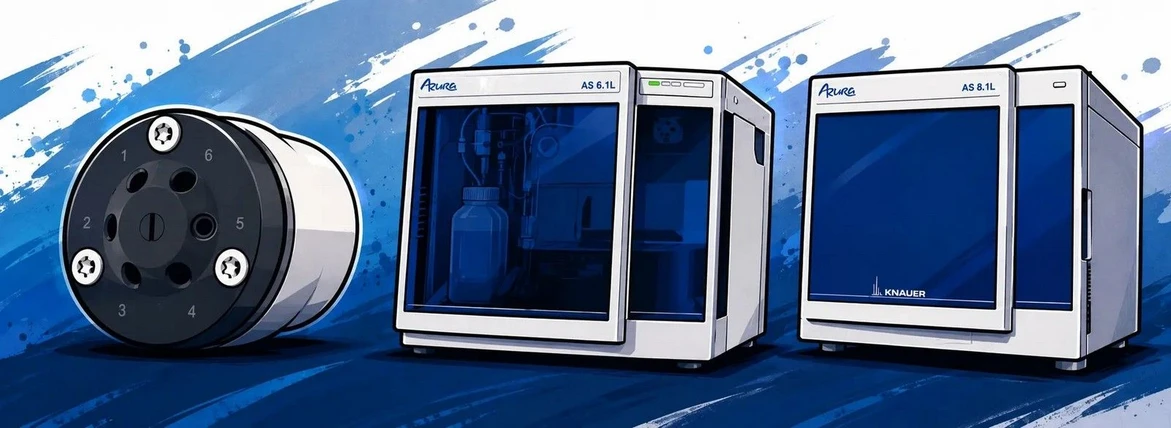
Today, KNAUER offers a broad portfolio of manually and electrically actuated valves, including two-position, multiposition, and special-purpose designs. The AZURA V 4.1 valve series can be integrated into modern chromatographic systems and adapted to a variety of applications.
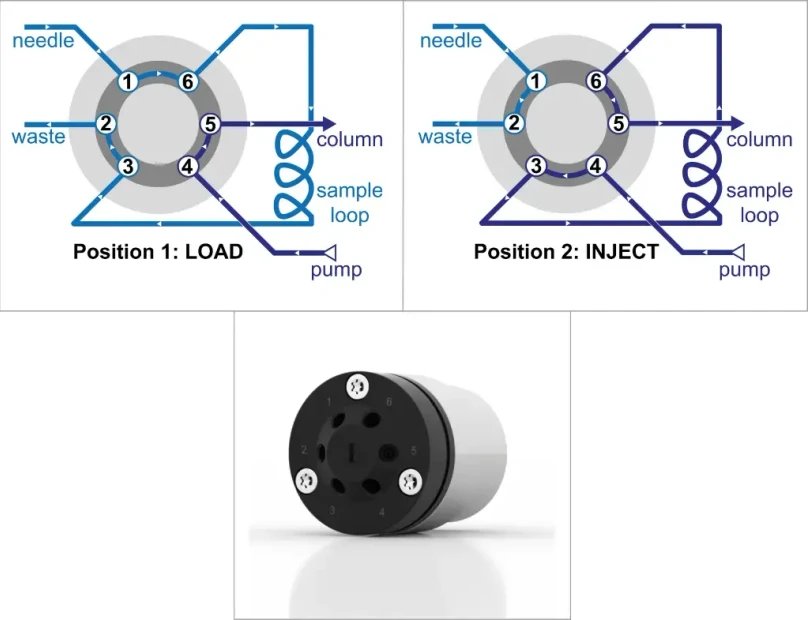 KNAUER: Fig. 1 - 6-port 2-position valve. Left: LOAD. Right: INJECT. Bottom: KNAUER AZURA V 4.1 valve.
Despite the major improvement represented by rotary injection valves, manual injection soon became a limitation as HPLC gained popularity in routine analytical laboratories.
Every sample still required an operator to physically rotate the valve. As sample numbers increased, this significantly limited laboratory throughput. Injection quality was also influenced by operator technique. Differences in sample-loop filling and the exact timing of valve switching could affect reproducibility.
Automation therefore became the logical next step.
Injection principles used in autosamplers
Autosamplers emerged during the mid-1980s, while the injection valve remained the central element of the design. As an interesting historical note, KNAUER had already become the first European manufacturer of modular HPLC systems in 1976.
An autosampler is an electrically operated injection system equipped with a sample storage area, usually designed for vials or multiwell plates. Its performance can be evaluated using several important parameters.
- Precision describes how reproducibly the system performs repeated injections. It is commonly assessed using the relative standard deviation (RSD) of peak areas or retention times from multiple measurements, often with five replicate injections.
- Linearity expresses whether the detector response changes proportionally with the injected sample volume. Ideally, increasing the injection volume step by step should produce a proportional increase in signal, with an R² value close to 1.
- Carryover occurs when traces of an analyte remain on the needle, within the valve, or inside the sample loop and subsequently contaminate the next analysis. Washing the needle and injection pathway can reduce this effect, although more extensive washing usually increases the total cycle time.
- Cycle time is another critical factor. Shorter cycles allow laboratories to process more samples per day and reduce both instrument occupancy and labor requirements. However, reducing cycle time can conflict with the need for additional washing steps to control carryover.
Modern autosamplers generally use one of three fundamental injection concepts.
Pushed-loop injection
The pushed-loop design is probably the closest automated equivalent of traditional manual loop injection.
In the LOAD position, the sample is first aspirated into a dedicated aspiration capillary and temporarily stored outside the main chromatographic flow path. The injection needle then moves to a low-pressure needle port and pushes the sample into the bypassed sample loop.
After the loop has been filled, the valve switches to the INJECT position. The sample loop is then connected to the mobile-phase stream from the pump, and the analyte is transported toward the analytical column.
KNAUER's Liquid Handler LH 8.1 uses this straightforward pushed-loop principle and can be configured for high-throughput applications. Its large sample capacity and overlapped injection capabilities support automated workflows with high sample numbers.
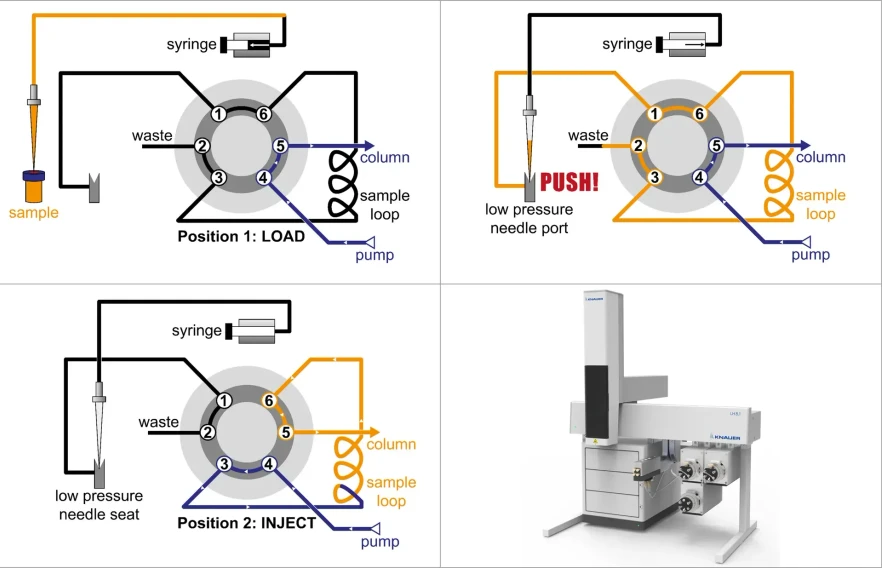 KNAUER: Fig. 2 Pushed-loop design. Left: LOAD. Right: Sample introduction (PUSH). Bottom Left: INJECT. Bottom Right: KNAUER Liquid Handler LH 8.1.
Pulled-loop injection
The pulled-loop design approaches sample introduction from the opposite direction.
Instead of using a separate aspiration capillary, the sample loop itself is used for aspiration. During the LOAD phase, the analyte is drawn directly into the loop. When the valve changes to the INJECT position, the sample loop becomes part of the main chromatographic flow path.
At the same time, the injection syringe can move to a wash position to reduce residual contamination.
Because the design eliminates the need for a low-pressure needle port and additional aspiration capillaries, it reduces the number of potential leakage points and can lower operating and maintenance costs.
KNAUER uses this robust and cost-efficient concept in the AZURA AS 6.1L autosampler. The instrument is available in several configurations, including temperature-controlled, biocompatible, preparative, and UHPLC versions.
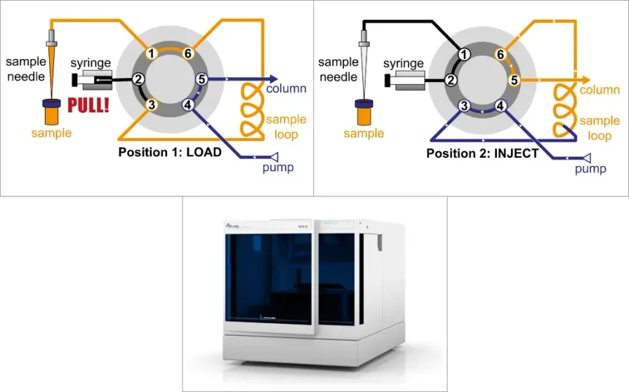 KNAUER: Fig. 3 - Pulled-loop design. Left: LOAD. Right: INJECT. Bottom: KNAUER autosampler AZURA AS 6.1L.
Full-loop, partial-loop, and µL pickup modes
Pulled-loop systems typically provide several injection modes, each offering a different compromise between precision, flexibility, and sample consumption.
- In full-loop injection, the entire sample loop is filled. This generally provides the highest precision and reproducibility because the injected volume is defined by the physical volume of the loop. The disadvantage is relatively high sample consumption, since the capillary between the needle and the loop must be flushed and the loop itself is usually overfilled to ensure complete filling.
- Partial-loop injection provides greater flexibility because different injection volumes can be selected without changing the sample loop. This approach is useful for applications such as dilution series. However, the tubing between the injection needle and the loop still needs to be flushed, resulting in additional sample consumption.
- The µL pickup mode is designed to minimize sample loss. Only the exact amount required for injection is aspirated, while transport solvent is used to move the sample through the tubing. This makes µL pickup particularly attractive when sample availability is limited or when precious samples are being analyzed.
Even with these designs, there remained room for improvement. The next development step focused on reducing sample consumption and carryover while shortening cycle times and maintaining high injection precision.
Split-loop injection
The modern split-loop design differs fundamentally from the previous concepts because the needle seat is located directly in the high-pressure flow path.
In the LOAD position, the system flow path is divided while the sample is aspirated directly into the injection needle. The outside of the needle can subsequently be washed to remove potential contamination before the needle enters the high-pressure seat.
At first glance, this design may resemble the pushed-loop configuration. The critical difference, however, is that the sample needle itself becomes part of the chromatographic flow path.
The needle seat therefore operates under full system pressure. In modern UHPLC applications, this can exceed 1,000 bar. Consequently, the needle and seat must form a highly precise high-pressure seal capable of maintaining reliability over many injection cycles.
Once the needle is positioned in the seat, the valve switches to INJECT and the sample becomes fully integrated into the system flow path.
Because the mobile phase continuously passes through the needle during the chromatographic run, the internal needle surface is extensively rinsed with eluent. In many cases, this eliminates the need for additional internal needle-washing steps and contributes to shorter cycle times.
With the AZURA AS 8.1L, KNAUER introduces a modern autosampler based on this state-of-the-art split-loop principle for HPLC and UHPLC applications.
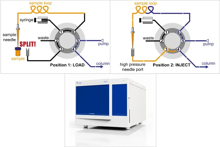 KNAUER: Fig. 4 Split-loop design. Left: LOAD. Right: INJECT. Bottom: KNAUER autosampler AZURA AS 8.1L.
The split-loop approach can substantially reduce sample loss, shorten cycle times, minimize carryover, and provide high injection precision.
However, these advantages come with slightly greater mechanical complexity. For reliable long-term operation, the high-pressure sampling needle and the corresponding needle seat should be maintained regularly, typically on an annual basis.
Pulled-loop versus split-loop
Both injection concepts have advantages, and the preferred design depends on the analytical application.
The AZURA AS 6.1L pulled-loop system offers greater mechanical simplicity and flexibility and generally places lower demands on maintenance. It also benefits from a comparatively low dwell volume.
The AZURA AS 8.1L split-loop system, on the other hand, provides advantages in sample conservation, cycle time, carryover performance, and injection precision.
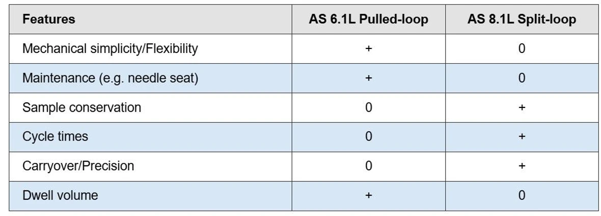 KNAUER: Tab. 1 Brief site-by-site comparison of KNAUER's AS 6.1L (pulled-loop) and AS 8.1L (split-loop).
The choice therefore depends on whether the priority is mechanical simplicity and flexibility or maximum efficiency in terms of sample consumption, speed, and injection performance.
Final thoughts
Sample injection may appear to be one of the simplest steps in an HPLC workflow, but its development shows how much engineering is required to introduce a few microliters of sample accurately and reproducibly into a pressurized chromatographic system.
From early manual injection through six-port rotary valves and the first autosamplers to modern pushed-loop, pulled-loop, and split-loop designs, each generation has addressed specific limitations of the previous approach.
The continuing evolution of injection technology reflects broader trends in liquid chromatography: laboratories expect higher throughput, better reproducibility, lower carryover, reduced sample consumption, and increasingly reliable unattended operation.
What appears today as a routine movement of a needle and switching of a valve is therefore the result of decades of development in chromatography, mechanical engineering, fluidics, and automation.
This version of the article was adapted from the original text using AI-assisted rewriting and editorial review.
Resources
- L.S. Ettre (2005). Csaba Horváth and the Development of the First Modern High Performance Liquid Chromatograph. LCGC. Volume 23. Issue 5.
- C. Horvath & S. Lipsky (1966). Use of Liquid Ion Exchange Chromatography for the Separation of Organic Compounds. Nature 211, 748–749.
- R. Majors & J. Baltrus (2020). The Analyical Scientist
- F. Steiner, C. Paul & M.W. Dong (2019). HPLC Autosamplers: Perspectives, Principles, and Practices. LCGC. Volume 37, Issue 8